Growcraft X5 DIY Assembly Instructions
Growcraft DIY Assembly Instructions Video
Watch the video first and then follow the photo instructions below for step by step guidance.
NOTE: X6 – 1000W Kit requires a different assembly process, please read the written instructions below.
Step By Step Picture Instructions Guide
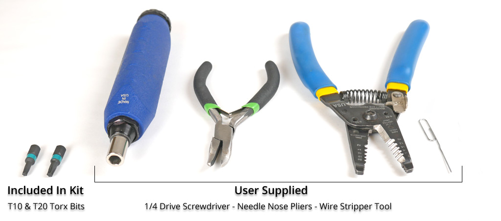
TOOLS
NOTE: The needle nose pliers are not required but are very helpful in inserting wires into pcb connectors.
STEP 1
NOTE: It is helpful to assemble on a flat surface like floor or table to make sure the light fixture is flat when assembled.
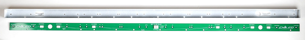
1-1: Position the Power Distribution Board inside one of the U Frames, making sure all of the holes line up:
NOTE: 1,000W kits come with 2 power distribution boards, one for each U Frame side. Each distribution board is then wired to 3 of the 6 Light Bars, as shown at the bottom of this page.
STEP 2
Note 1: The Light bars in your kit have the LED Boards already secured to the heatsink, only the outside edge holes are left without screws. These holes are later used to secure the PCB Covers.
Note 2: The LED board has a connector on each end and although you can use either one, please note that on one side the (+) Positive connection is closest to the edge and on the other side the (-) Negative connection is closest to the edge. Please be sure to have either all positive or all negative facing the same U Frame side.
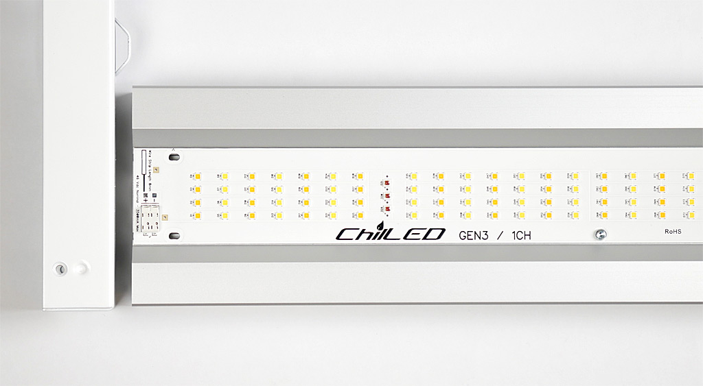
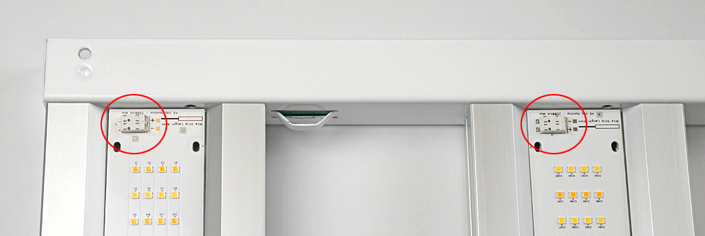
Image below illustrates how the board sides can be mixed and have the connections reversed (left LED board has positive connection closest to the U Frame and the Light Bar on the right has the negative connection closest to the U Frame.
2-1: Align all of your Light Bars against the back side of the U Frame.
STEP 3
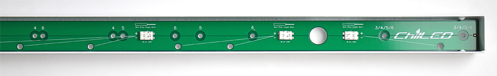
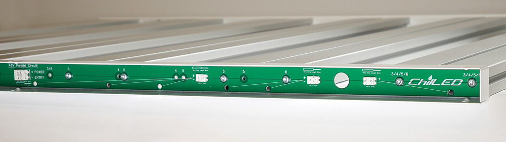
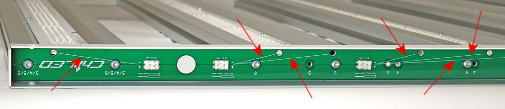
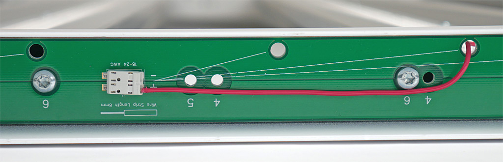
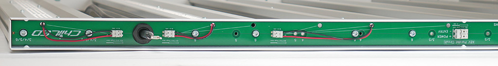
3-1: The Power Distribution Board has reference numbers on top of the extrusion holes. If your kit is a X6, then use all of the “6” holes to secure your Light Bars. If your kit is a X5, then use all of the “5” holes to secure your Light Bars and so on.
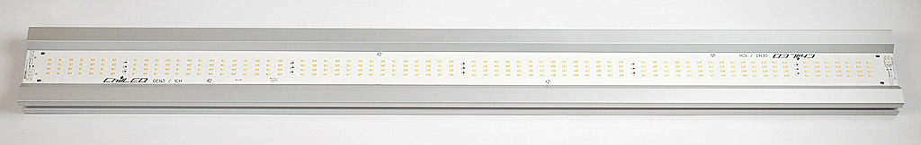
3-2: Once the Power Distribution Board side is secured to all Light Bars, place the other U Frame on the opposite end and secure using the holes closest to the Light Bar holes. Congratulations, you now have a fully assembled framework!
STEP 4
4-1: Flip your Growcraft light framework over to the other side so that the LED boards are facing up.
Note 1: Use the supplied 20 AWG red and black solid core wires to wire the Light Bars.
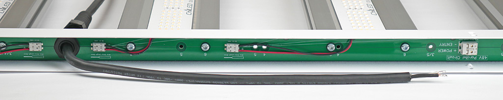
4-2: Strip the red wire about 8mm, insert the wire through the U Frame hole and push into the (+) Positive side of the connector. Using pliers helps make this process easier and more precise.
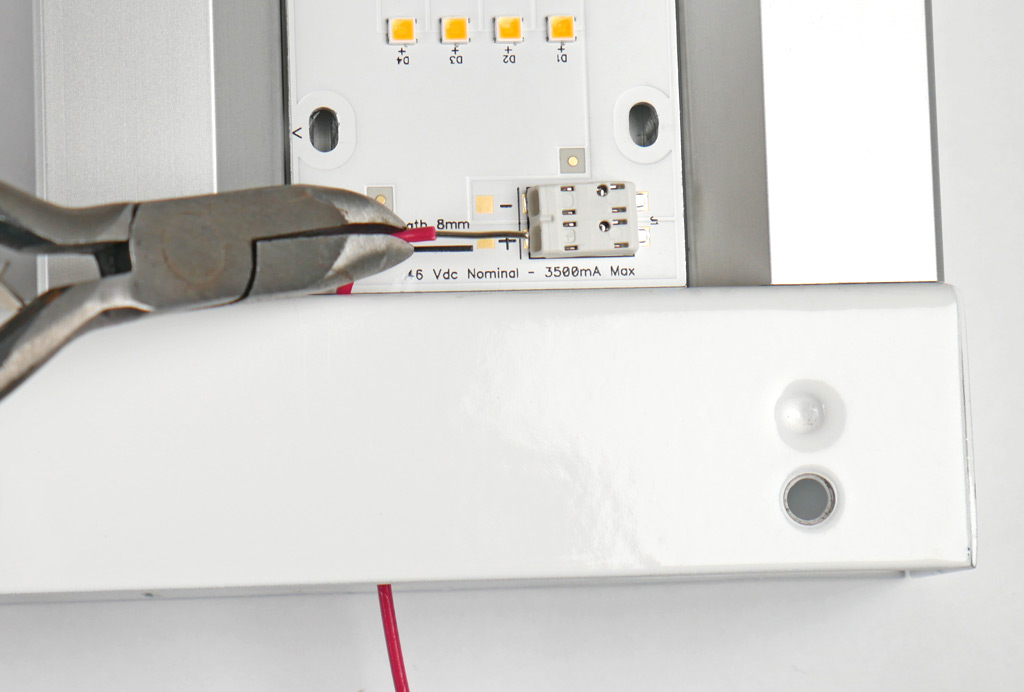
Note 2: The Power Distribution Board has helpful guide lines that show you which connector to use for each Light Bar hole (see the red arrows).
4-3: Bend the red wire to give it a bit of slack and cut at about the end of the connector. This will give you enough length to strip this end and insert it into the connector indicated on the Power Distribution Board.
4-4: Repeat steps 4-2 and 4-3 until you have all your connections made, then proceed to step 5.
STEP 5
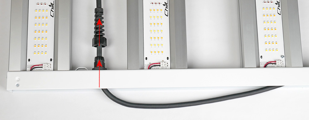
5-1: Disassemble the Strain Relief Cable Gland as shown below.
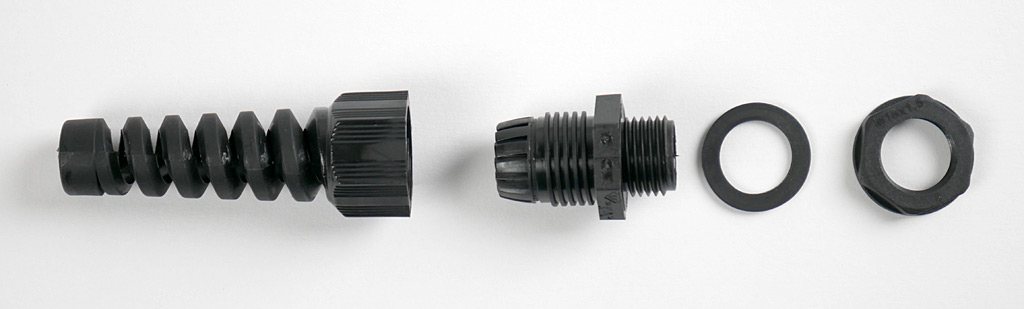
5-2: Slip the Strain Relief Cable Gland components shown below over the 48Vdc LED Power Cable. Be sure the parts are facing the correct way.
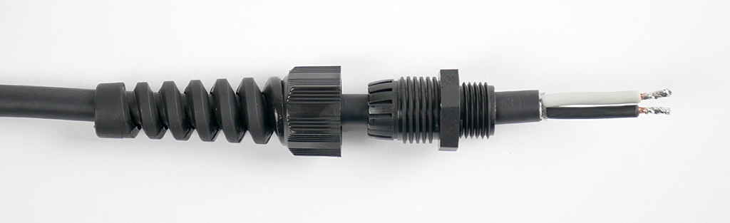
5-3: Insert the 48Vdc LED Power Cable through the hole on the wired side of the U Frame and Power Distribution Board. Then slip on the rubber gasket and nut as shown below.
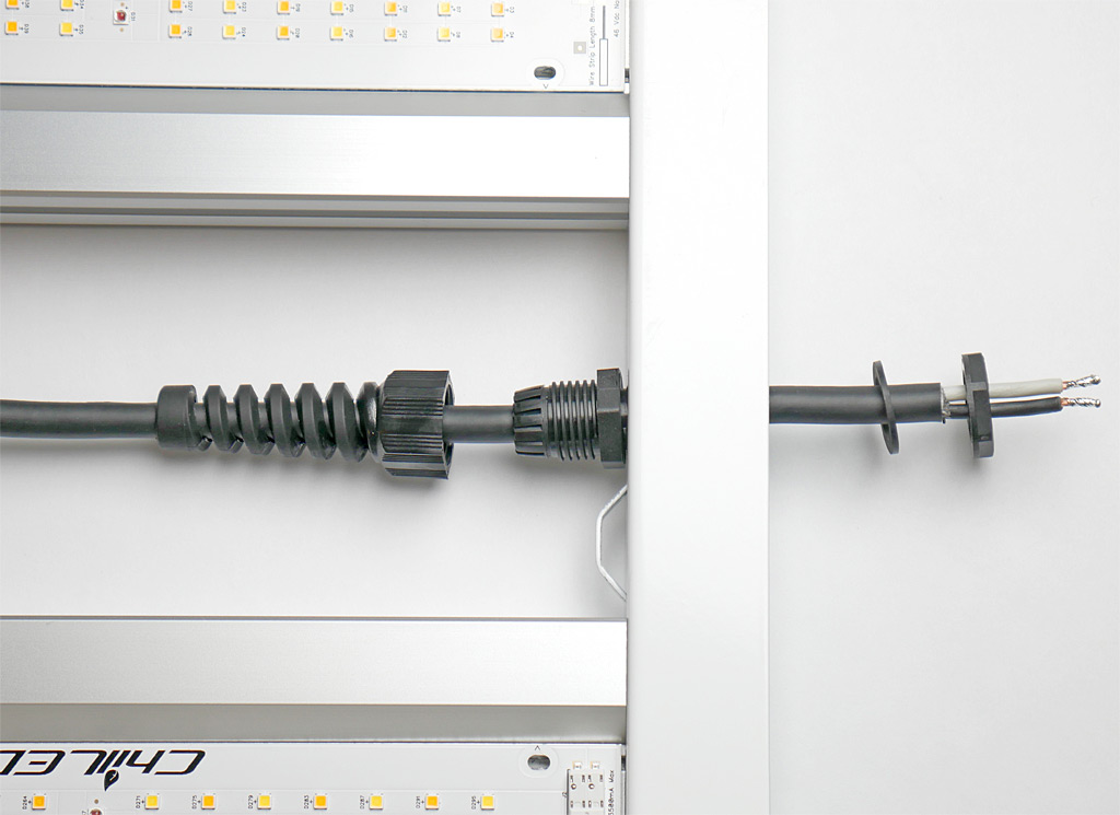
5-4: Now assemble the Strain Relief Gland components on both sides of the U Frame. Once hand tight, the rubber gasket will hold the nut in place and you can further hand tighten the Strain Relief Gland on the outside of the U Frame.
5-5: Pull enough cable through the Strain Relief Gland to easily reach the main Power Connector in the center of the Power Distribution Board.
5-6: Using pliers, if available insert the white wire into the (+) Positive side of the connector and the black wire into the (-) Negative side of the connector. Be sure to test secure connection by gently pulling back on the wire, if it slips back then it wasn’t inserted far enough into the connector.
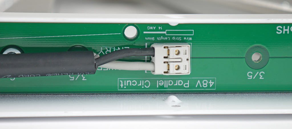
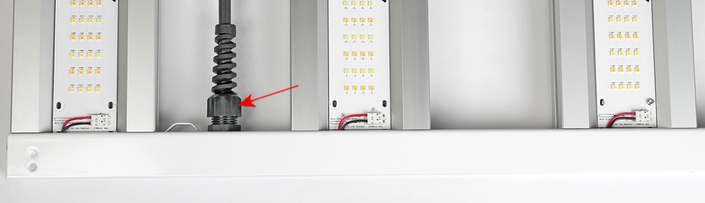
5-7: Pull the cable back through the Strain Relief Gland to remove most of the slack in the cable inside the U Frame but don’t stretch tight, there should be no strain on the Power connector.
5-8: Tighten the outer shell of the Strain Relief Gland to secure cable in position.
STEP 6
6-1: Insert the Cover into the U Frame – Text should appear upside down when LED boards are facing up, this will then have the text facing right side up when the light is facing down toward your canopy. (shown incorrectly in the images below)

6-2: Install the M3 Countersunk screws on both sides of the U Frame and both ends of the Light Frame.
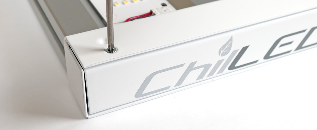
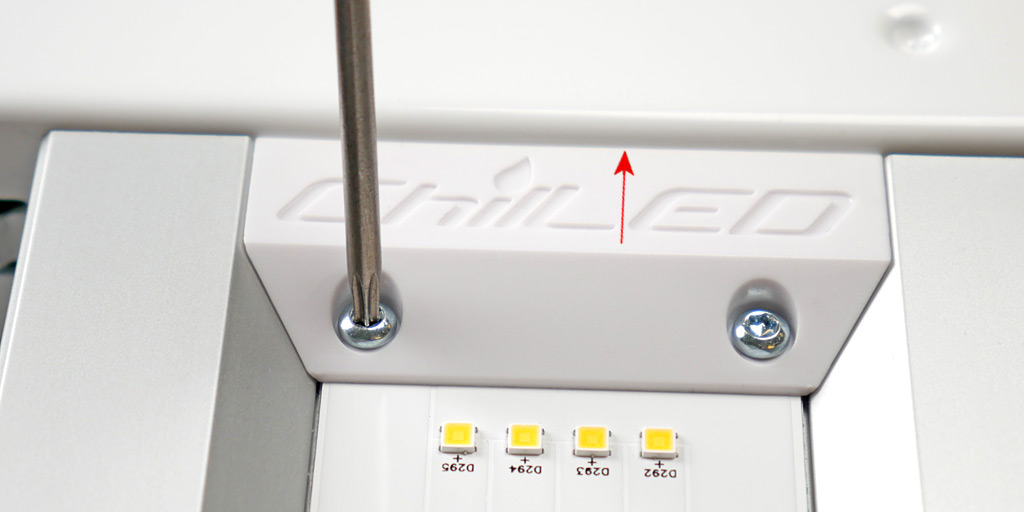
6-2: Position the PCB Cover in place and while pressing it against the U Frame (as shown by arrow below) secure in place with the supplied M3 8mm Plastite screws.
STEP 7
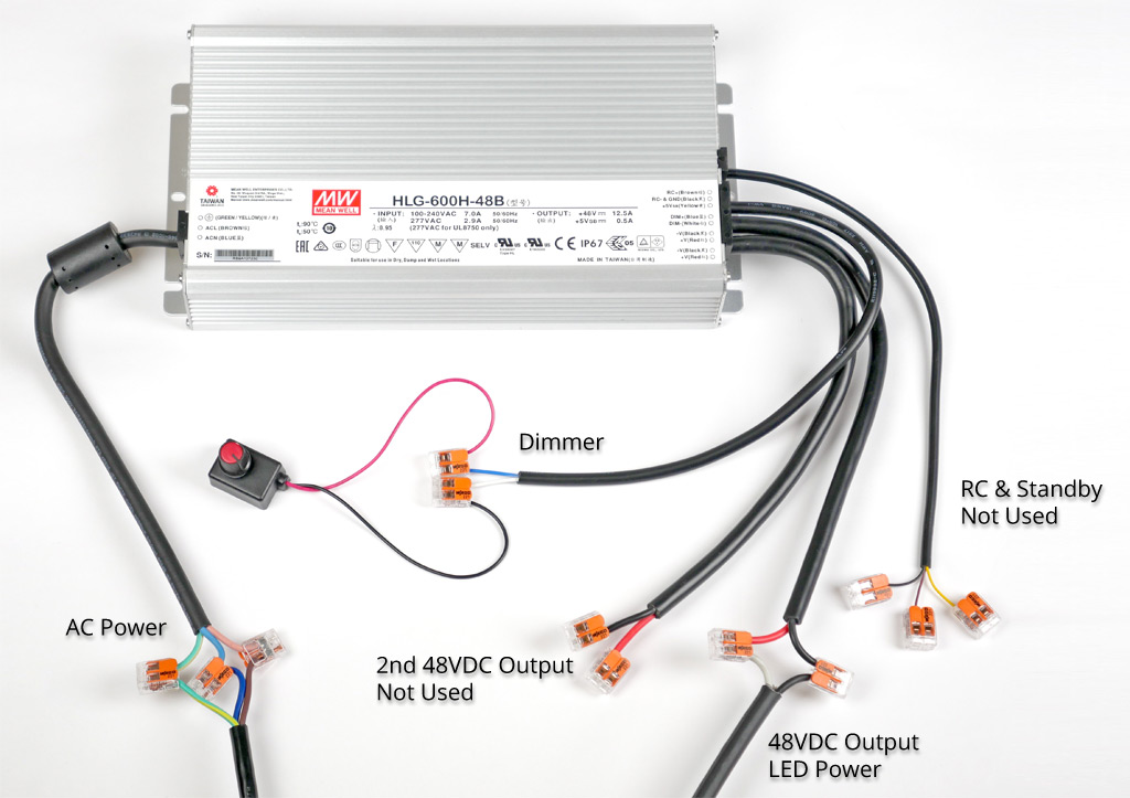
7-1: Final step is to connect the LED Driver to the Growcraft LED Grow Light. Wiring shown below is for the Mean Well HLG-600H-48B LED Driver, if you purchase a lower wattage kit you may have a different Mean Well Driver. The wiring is the same for all drivers except the HLG-600H-48B has 2 additional cables that are not used.
Follow the layout below to connect your LED driver to the light fixture.
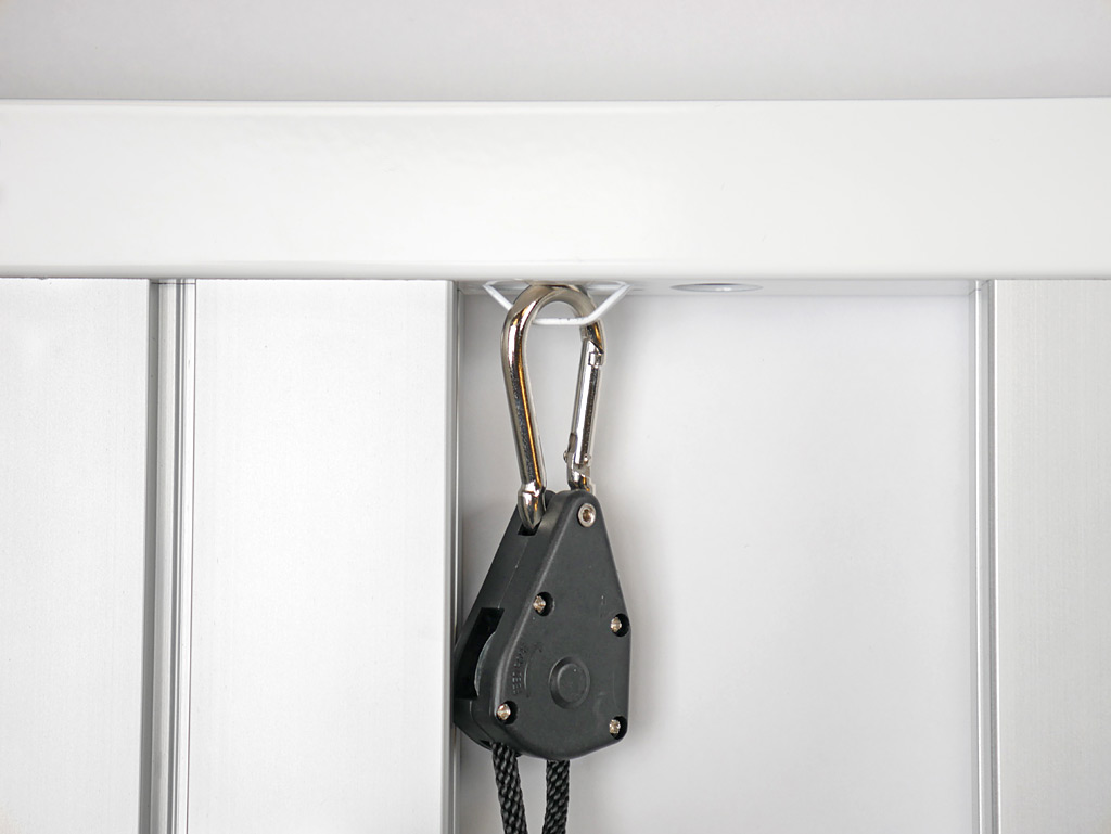
7-1: Connect your supplied 4 Rope Ratchets to each hanging loop on both U Frames.
Congratulations! You should now have a fully assembled ChilLED Growcraft LED Grow Light!
1000 Watt Dual Driver Setup
The 1000 Watt DIY kit uses 2 x HLG-480H-48B drivers. Each driver powers 3 light bars on opposite ends of the light – see photo below:
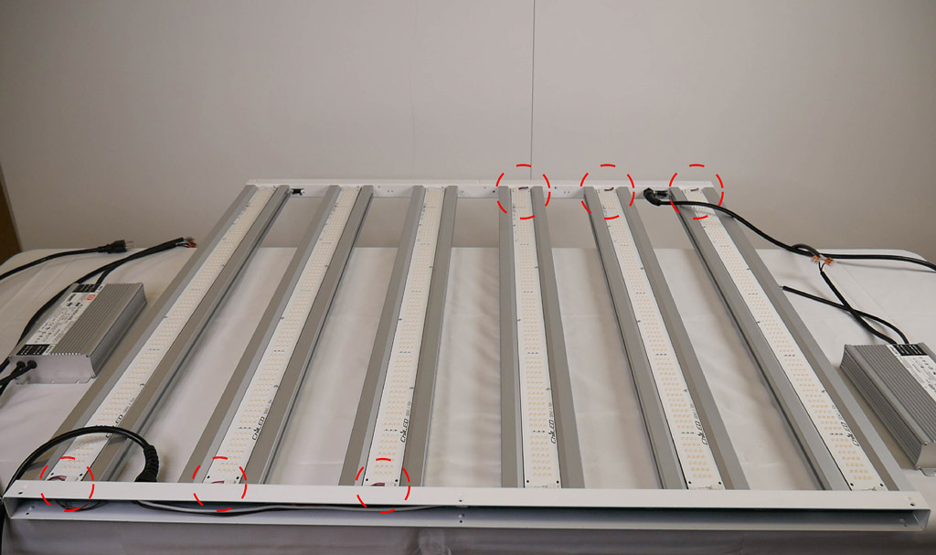
Two Power Distribution Boards are provided, one for each U Frame. Each side’s Power Distribution Board is connected to one HLG-480H-48B driver and 3 adjacent Light Bars, as shown in above photo.